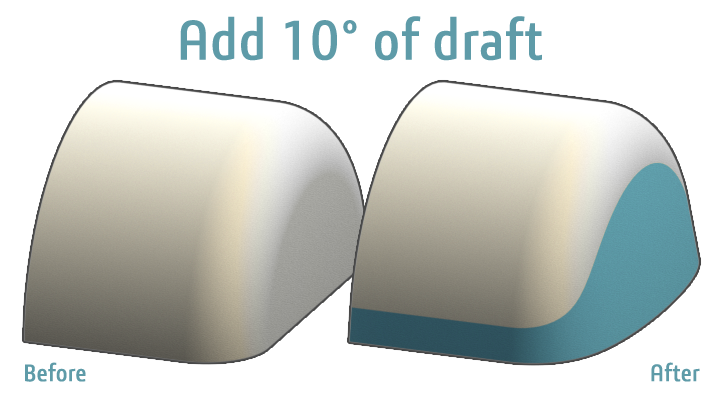
Just like previous modeling challenges, give this one a shot on your own before scrolling down and reading some of the possible solutions. As always, feel free to share even more tips and tricks in the comments below. Today’s challenge is to add 10 degrees of draft to the end of this 2016 cylindrical SOLIDWORKS model while respecting the current location of the fillet. This may sound easy, but drafting around curved faces such as fillets can be trickier than it seems.
Draft Before Fillet
Typically, the best practice for adding draft is to do so before adding fillets. Just like you learned in Solid Modeling 101, save fillets for the end of your feature tree. They complicate models by multiplying the total quantity of faces and edges, and should be used as a finishing touch.

- Drag the rollback bar above the ‘Fillet’ feature
- Use the ‘Draft’ feature on the end face of the cylinder while using the bottom face as the ‘Neutral Plane’
- Drag the rollback bar back to the bottom of the feature tree to reapply the ‘Fillet’ feature
This would normally be an acceptable approach, but in this challenge, we do not have the liberty to alter the original location of the fillet. Let’s try this again by adding the draft after the fillet feature.
Ruled Surface
The intent of a fillet is to smoothly transition between two faces that would otherwise form a sharp corner. By definition, fillets need to be tangent to their surrounding faces. Therefore, we cannot draft the end face before cutting back the filleted face to the theoretical tangential edge that would be formed by a 10 degree draft angle.

- Create a ‘Plane’ at a 10 degree angle from the bottom face of the model
- Use the ‘Split Line’ feature in ‘Silhouette’ mode to divide the filleted face while referencing the previously created plane
- ‘Delete’ the end face of the cylinder as well as the adjacent face of the fillet using the ‘Delete Face’ command
- Use the ‘Extend Surface’ command to grow the open edges of the bottom face
- Add a 10 degree ‘Ruled Surface’ to the open edge of the filleted face with respect to the bottom face of the model while overlapping it
- Generate a solid from from the ‘Internal Region’ using the ‘Intersect’ feature
This approach brings us much closer to a solution, but falls short in a few ways (besides simply taking too many steps):
- It leaves us with a surface that does not maintain a precise 10 degree draft angle throughout
- It neglects the fact that the edge of the cylinder converges to a 0 degree draft angle (i.e. less than the required 10 degrees) as it meets the top plane of the model
- If we were to hide all tangent edges or display ‘Zebra Stripes’, we would notice the Ruled Surface is not tangent to the filleted surface as it should be
Parting Line Draft
Knowing we have to account for draft throughout the entire model, let’s try using a more advanced mode of the ‘Draft’ feature to simplify our workflow.

- Use the ‘Split Line’ feature in ‘Silhouette’ mode to split the filleted face and the cylindrical face at an angle of 10 degrees
- Use the Split Line’s model edges as the ‘Parting Line’ while adding a 10 degree ‘Draft’ feature
- ‘Delete and Patch’ the end face of the cylinder using the ‘Delete Face’ command
Not only is this method quick and easy, but it leaves us with the most desirable results – exactly 10 degrees of draft on all of the new faces we added to the model. Perfect!
Originally posted in the SOLIDWORKS Tech Blog.